Torsion in Rectangular Prism
I hope to expand on this post in the future and relate the equations that are derived for find stresses and strains of a rectangular prism (bar) to that of an I shaped section. Then relating that to AISC’s design guide 9 (see here for AISC design guides).
Explanation of Stress – Strain Behavior
We recall that for circular shafts that section planes remain plane (and circular) and that all radii lines remain straight; no bulging or cupping. Therefore shear stress occurs along a set of concentric circles. This however is not possible with a rectangular shaft as if the shear stress was tangent to a set of concentric circles the shear stress would not be perpendicular to the boundary. The shear stress must be perpendicular to the boundary. Why? Because if it is not than components perpendicular to the boundary will exist which creates a ‘complementary’ shear stress on the outside free edge of the prism (see Figure below). From this we conclude that the shear stress must be perpendicular to the periphery (boundary) of the section.

Torsion – Shear Stress in Non-Circular Prism
We can also conclude that the shear stress must also be zero at the corners as neither one of the two perpendicular components can exist (see Figure below).
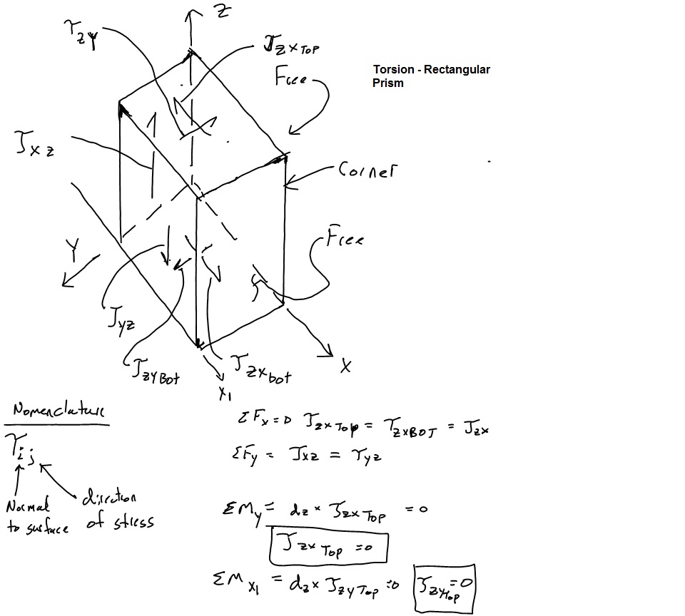
Torsion – Shear Stress in Non-Circular Prism Corner Stress
For a circular section it was also shown that the plane cross sections remained undistorted in their own plane. Meaning there was no distortion of the concentric circles and radii, the radii remained straight. We cannot directly prove this to be true for a non-circular prism but we can look at what it means if we assume there is some distortion.
For a non-circular section, we imagine a perpendicular grid pattern across a section. These grids then become distortion in the plane of the section. These shear stress then cause shear stresses to appear on sections parallel to the longitudinal axis. These stresses do not add up to a twisting moment and are ‘useless’. This does not constitue a proof but it should be noted that nature opposes an applied action (Torque) through the minimum elastic energy i.e. the simplest way possible or via the simplest stresses possible. It is shown via energy methods that these stress do NOT occur and or reasoning is correct.
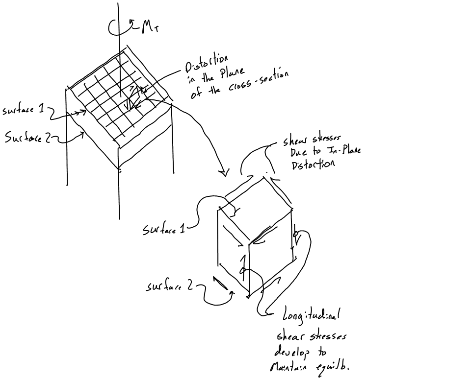
Torsion – In Plane Distortion
Calculating Stress
Too be continued….. Refer to Roark for now 