Analysis of Offset Surcharges on Retaining Walls Using Elastic Methods
Offset surcharges are always up for some debate. Which method to use? What is the line of influence? Is the wall flexible or rigid? Well in this segment we will cover the analysis of surcharge loads on retaining walls using elastic methods. You may commonly here this as a Boussinesq analysis or a Boussinesq as modified by Terzaghi or Tang. Also other equations have been produced by Spangler and Mindlin. Trying to wrap you head around all the different equations and who did what can be confusing. We will try to straighten some of this out and present some of the different approaches and how most of the equations are similar but the equations are presented slightly differently.
Constraints and Assumptions
There are generally 4 types of surcharges considered – Point load, Line load, Strip load and Area load. Point loads and area loads have a finite length. Line and strip loads are assumed to be of infinite length parallel to the wall. The back slope is generally considered to be flat. Elastic methods do not consider any soil parameters such as effective shear strength or wall friction. The only way to try and account for different soil types is by adjusting Poisson’s ratio or adjusting the factor of safety. However most of the theories assume a Poisson’s ratio (u) of 0.5 which simplifies the analysis, but more on this latter.
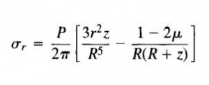
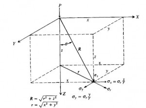
The basis of the elastic methods discussed below is Boussinesq’s equation for a surcharge on a semi infinite mass
Equation 1:
Where:
P = point load
v = Poisson’s ratio
History
Most of this is from Bowles 4th Edition Foundation Analysis and Design.
1936 Spangler – Performed experiments to measure the lateral pressure on a wall due to point loads form a truck behind a rigid retaining wall. Spangler used Boussinesq’s equation with u=0.5 and found that the actual lateral pressure was approx 2x the pressure found by equation 1 with u=0.5. Bowles points out some flaws of this experiment – loose soils with a wall of ‘finite’ length and ‘old’ technology used in the load cells.
1936 Mindlin – Discusses the results of Spangler. He explains that the 2x factor could be due to the rigid wall producing a mirror load effect. This reasoning is disputed by Bowles.
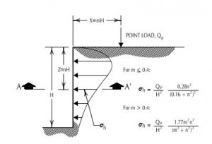
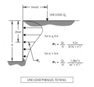
1954 Terzaghi – suggests 0.4*H (wall height) is a critical distance behind the wall where two different equations should be used for point loads and line loads. Terzaghi proposed (2) different modified boussinesq equations for point and line loads both using v=0.5.
1962 Teng – Similar modification claiming that the pressure on rigid walls for strip loads should be 2x the results obtained by the ‘integrated’ Boussinesq equation. Some also credit Teng the strip load equation shown below as a plastic’solution as opposed to the Boussinesq solution which is an elastic solution (See Civiltech Software Design Manual and Foundation Design by Wayne C. Teng 1962).
1972 – Rehnman and Broms showed that when the soil behind the wall was dense the lateral pressure from point loads was much less than with loose soils. Also gravelly backfill’s produced larger lateral pressures than finer-grained soils. This observation would mean soil state and Poisson’s ratio are significant.
When and How to Apply Elastic Methods
First the how – The equations presented below give pressures at a certain height on the wall. Therefore it is suggested that a program or spreadsheet is made that uses these equations to find pressures at set intervals or segments of the wall (sigmah). Then the force is found by multiplying the height of this segment by the pressure (Fi=force at elevation ‘i’ = sigmah * hseg). Then you solve for the height above the bottom of the wall to this segment (yi = height to force, Fi). Then you solve for the resultant force and it elevation. Fh=sum(Fi’s) Then find the elevation Ybar = Sum(yi’s * Fi’s)/Sum(Fi’s). This is similar to finding the centroid of an area by parts. This pressure/force is then superimposed on the soil pressure.
Zone of Influence
Second the when – This is a much more difficult question to answer. There are many different ways that an offset surcharge maybe handled see here for a more indepth look. So if we are specifically looking at when to apply elastic methods the answer would be – anytime. We can superimpose the results of the elastic method results on to the soil pressure as would be found using Rankine or Coulomb equations (see here for refresher). However elastic methods will yield a horizontal force for any surcharge applied at any distance behind the retaining wall. This may be overly conservative however it is up to the engineer to determine what distance beyond the wall that the surcharge would have no affect on the retaining wall. Usually this information is given in the governing code. Some examples – many use the Rankine or Coulomb failure plane as the determining distance however a trial wedge may give different results when finding the failure plane angle. Edward White has suggested that pressures may distribute down at 1V:1H (See Foundation Engineering Handbook by Hans F. Winterkorn and Fang). Sometimes a 2V: 1H is used as in a Meyerhoff or Boussinesq bearing pressure distribution. While a 2V:1H has been found accurate at short depths (See Bowles 3rd Edition p172) and is usually conservative when finding vertical stress at a certain depth but can be unconservation when finding horizontal stresses. Most rail road design manuals suggest at 1.5H:1V influence line. The NCMA recognizes a 2H:1V as a conservative estimate to find the horizontal distance to which you may disregard surcharge loads.
Elastic Method Equations
Below are the ‘typical’ equations used in most design manuals for using elastic methods. There are links to other posts which will give further discussion, examples and spreadsheet calculations. The equations assume rigid walls (pressures maybe less for flexible walls, Civiltech Software recommends 0.5 for flexible, 0.75 for semi-flexible and 1.0 for rigid – see further discussion), a Poisson’s ratio of 0.5, and the pressure maybe combined by method of superposition.
Nomenclature:
σh= horizontal pressure
H = Height of wall (excavation)
x1 = m*H = distance to surcharge (point load, line load, strip load)
zi = n*H = distance from top of wall to elevation under consideration
Q = point load or line load surcharge
q = uniform surcharge
Point Loads
Boussinesq equation as modified by Terzaghi.
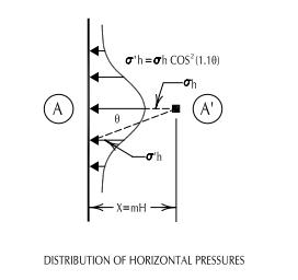
To evaluate a point at an angle to the point load along the wall:
See here for a thorough discussion
Line Loads
See here for a thorough discussion
Strip Loads
See here for further discussion.
Area Loads
Will update shortly
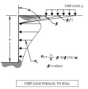
All the text books I’ve seen and even NAVFAC will not tell you that beta in the equation is in radians. Why is that?
I’m not sure why they don’t tell you this but the reason it needs to be in radians is most likely due to the way the equation was derived. The strip load equation is the result of integrating the point load equation and most likely done using radians as opposed to degrees. Therefore it is ‘scaled’ for radians. Look at the first reply here: http://mathforum.org/library/drmath/view/64034.html for more discusion on radians vs degrees. Hopefully that answered your question?
Thank you.